


 Download(20.78MB)
 1.0.0.6.7
 4.34MB
8.8
Body of an Internal Combustion Engine for Performing The Air-Fuel Mixture
1. Describe and control the operation of the circuits of a carburetor
2. Check and adjust the idle
3. Set the carburetor circuits to meet the depollution standards
4. Define and know the origin of harmful gases of the exhaust of petrol engines.
5. Master the importance and usefulness of anti -pollution standards.
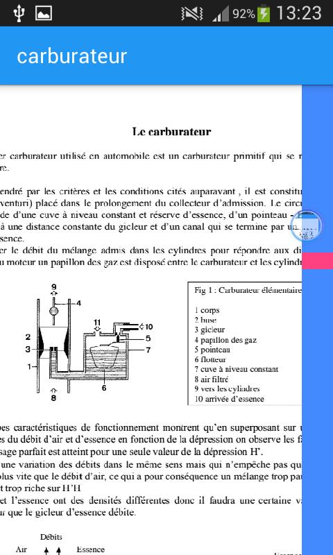
1 body 2 nozzle 3 Gucler 4 Gas butterfly 5 Binge 6 Float 7 Tank with constant level 8 Filtered air 9 towards cylinders 10 petrol arrives
Low temperature start (approximately 0 °)
Resumption
Low -speed
Idle
Maximum power
Economic driving
Gicler drowned
1 body 2 nozzle 3 Gucleur 4 Gas butterfly 5 Binge 6 Float 7 Tank level 8 Filtered air 9 towards cylinders 10 Petrol arrorsage 11 Atmospheric pressure 12 Automaticity Automaticity
The idle circuit
It allows the rotation of the engine when the vehicle is stopped but also the progression when the idling of the normal walking and during the decelerations the fuel supply system is taken either: directly in the tank: it will bear the name of "bijet system" since it will flow both in slow motion as in normal. That in the pipeline of the main circuit and after the nozzle: it will bear the name "monojet system" and will not debite during normal walking
1 Air caliber 2 Ralentine jars 3 Main jet 4 Wealth screws 5 by pass 6 Passement screw Gas butterfly 7 non -reversal orifice
The sweeping slowdown
The idle to co constant
Wealth correctors
1 suction valve 2 Roting and control spring 3 Adjustment lifted 4 control lever 5 Membrane 6 Spring 7 Retry valve 8 injector
1 membrane 2 depression taking
Cold starting devices
The starter
Ice Starter Principle
1 Emulsion output channel 2 Petrol pipe 3 Ice 4 Air jet 5 6 rotary ice cream 7 Petrol jet 8 reserve (well)
Ice system 1 fuel input 2 notch 3 Starter command 4 Cold starting position 5 Intermediate position 6 Provision of the Starter Coupé
The starting component
1 Departure component 2 Lever 3 Reminder spring 4 Starting air entrance
1 component 2 valve 3 spring
1 ovad (opening of the after departure shutter) 2 membrane 3 Ovad 4 -spring adjustment screws
The spring holds the membrane to the rest position for the start of the engine. As soon as the last can be taken care of, depression increases quickly and makes the membrane back up to a value adjusted by the stopped screw.
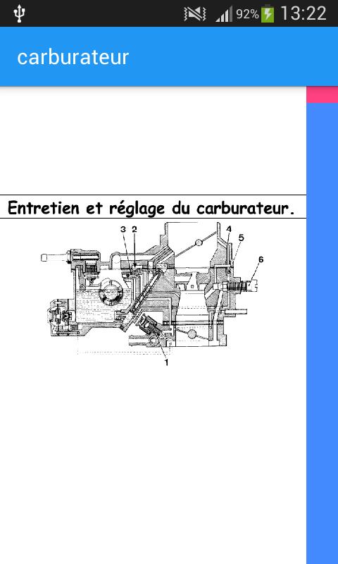
Carburetor adjustment
The adjustment is made after a carbberry layout and before it is based on the engine. For these pre -settings we will use specific tools such as rods, calibers and angle measureers. The settings to be made relate to: the position that the butterfly of the gases takes during: the idle the cold departure, positive opening and the interbow of the shutter at the level of the tank The recovery pump to make these settings it will be necessary to refer to the data of the manufacturer's technical sheets
Adjusting the level of the tank: the needle and the float having been checked, the height that exists between float and the plane of the tank joint must be controlled by calibers or rods. This height can be adjusted: by formulas of the float rocking; by action on the needle attack tongue; by modification of the thickness of the pointe joint.
Recovery pump settings
 Similarity
January 21, 2026
January 21, 2026
January 21, 2026
January 21, 2026
January 20, 2026
January 20, 2026
January 20, 2026
January 19, 2026
January 19, 2026
January 19, 2026
January 19, 2026
January 18, 2026